
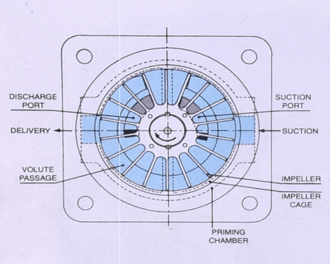
The initial prime is accomplished by partially filling pump priming chamber with liquid as in Sketch 'A’. This shows pump not in operation but the initial prime can just as readily be effected while pump is actually running.
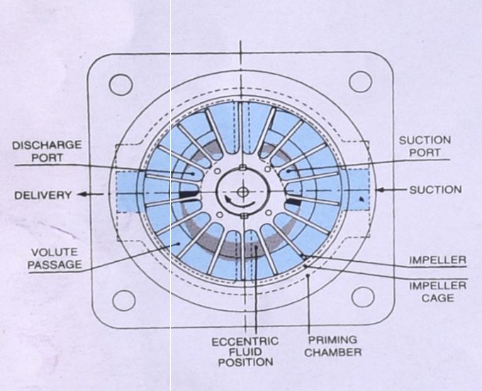
The rotation of the impeller throws the liquid out between the blades towards the periphery by centrifugal force and at the same time imparts velocity to the liquid in the volute passage. The air being lighter remains in the centre of the cage. The volute has its maximum cross-sectional area between points at the bottom section of the impeller cage and decrease in area in either direction from this point.
As a pair of blades approach the discharge, the liquid is forced (by centripetal action) between them, down towards the centre due to the decrease cross-sectional area of the volute. This, in effect, provides a positive liquid piston action, pushing the air at the centre out through the discharge port and into the discharge pipe. The space between blades as they pass the extreme end of the discharge port, is now completely filled with liquid which is retained therein until the bridge or sealing surface between the discharge and suction ports has been crossed.
Once past the bridge, however, the liquid between the impeller blades is thrown out into the volute passage which increase in cross-sectional area.
This again provides the positive liquid piston action away from the centre of the pump, reducing the pressure over the suction port and air in the suction pipe is forced up into the pump as a result. This action, continues until all air has been evacuated from the suction line. Sketch 'B' shows -the air pumping stage and illustrates the eccentric liquid ring effect formed within the casing. This actually amounts to definite suction and discharge strokes of liquid piston within the pump ans is the reason for its positive timing action.
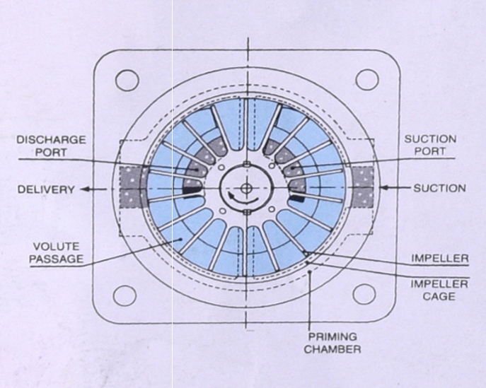
After all the air has been evacuated from the suction line, the pump commences and will continue to pump liquid on exactly the same basis, this being illustrated in Sketch 'C'. lf the pump breaks suction, it will pump air until suction line is again submerged and then pick up the liquid again. No foot or check valves are needed. Sketch 'C' shows bubbles of air in the liquid flowing through the pump. It has great air handling ability. Minor leaks in the suction line, therefore, do not affect operation neither will a loop in the suction line.
When the pump is stopped the liquid is retained in the pump casing and the pump is ready without any further priming to start pumping.
Mechanically the pump is similar to a conventional centrifugal design only two operating parts, impeller and shaft with the same running fit. Therefore, its service life will be the same as that of a centrifugal pump under same working conditions.
Naklank Engineering In Gundlav GIDC, Valsad, India, Happens To Be An Organization of Repute Having A Rich Expertise of 15 Years In The Field of Manufacturer of Chemicals Process Pumps. See More...
Shed No. L / 211 / 2, 2nd
Phase, G.I.D.C., Gundlav - 396035, Valsad, Gujarat.
9426892939 / 9978444236
[email protected] [email protected] [email protected] [email protected]